
CTIA certification LTE Category M1 OTA and LTE NB-IOT OTA test
1. LTE Category M1
Test program
Measurement location and EUT shall be configured according to relevant regulations. The power of EUT radiation should be measured by calibrated accurate radio frequency measuring instruments (for example, spectrum analyzer, or measuring receiver or power meter).
Note: See for power measurement considerations.Appendix d。
The LTE simulator and EUT shall use 3GPP TS 36.5211 and 3GPP TS according to section 6.2.2EA of 3GPP TS 36.5211 (maximum output power of UE in UE category M1).
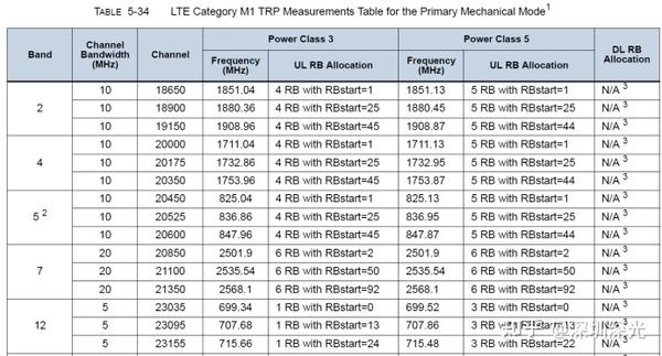
The default settings specified in 36.508 (if applicable) are configured, and the uplink reference measurement channel defined in Tables A.2.2.2.11b and A.2.3.2.11b and Table 534 of 3GPP TS 36.5211 is used. The UE output power should be measured using the test procedure in Section 6.2.2EA of 3GPP TS 36.5211
As defined in Table 534, different frequency pairs (FDD, HDFDD; UL uplink /DL downlink) or frequency (TDD) and RB allocation.
Forearm and/or free space testing shall be conducted according to the equipment type specified in Appendix O. See for forearm test requirements Appendix q . Perform each test on all specified frequencies and RB allocations, while extending and retracting EUT antenna (if applicable).
Standard
The results shall be reported in accordance with Appendix B using the quality factors given in Appendix B.3.
The pass/fail standard of LTE M1 needs further study, and different pass/fail standards may be formulated for different equipment types/use cases. The report should include the results of applicable use cases, including free space and/or wrist-mounted configuration allocated across all channels and RBs.
EUT is used as reference information in the main mechanical mode and (if applicable) in the non-main mechanical mode.
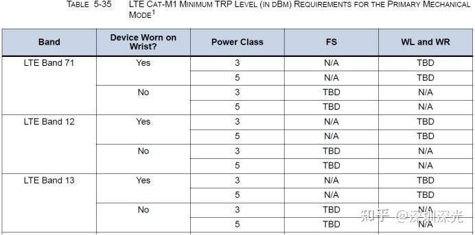
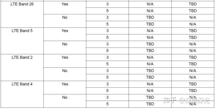
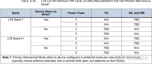
The following figure 5-35 requires mode 1 for the minimum TRP level (in DBM) of LTE CATM1 for major mechanical equipment.
2. LTE Category NB1 (NB-IoT)
Test program
The survey location and EUT should be configured in accordance with the provisions in Appendix A. EUT should use calibrated, precise RF measuring instruments (for example, spectrum analyzers, or measurement receivers, or power meters).
Note: See for power measurement considerations Appendix D。
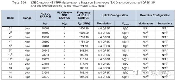
The LTE system simulator and EUT shall use the default settings specified in 3GPP TS 36.521 ‑ 1 and 3GPP TS 36.508 (if applicable) according to the maximum output power in section 6.2.2f (UE category NB1) of 3GPP TS 36.521 ‑ 1, and use appendix a.2.4 and table 5 ‑ 36 of the defined uplink reference measurement channel 3GPP TS 36.521 ‑ 1.
The test procedure in section 6.2.2f of 3GPP TS shall use 36.521 ‑ 1 to measure the output power of UE.
The Trp measurement shall use the NB1 single machine (SA) mode and the test channel configuration described in Table 5 ‑ 36.
Note: Compared with LTE, the frequency difference between the test channel (FUL) and the actual channel is very small (< 100kHz). Therefore, the power measurement should be completed on FUL.
The following figure 5-36 LTE category NB1 TRP measurement table is used to use /4 QPSK (15 KHZ subcarrier spacing in main mechanical models)
Standard
The results shall be reported in accordance with Appendix B using the quality factors given in Appendix B.3. Appendix B.1 contains a pass / fail OTA table for LTE category NB1.
The pass/fail standard of LTE NB1 needs further study, and different pass/fail standards may be developed for different equipment types/use cases. The report shall include the results of applicable use cases, including the free space of all relevant channels and/or the wrist-worn configuration EUT in the main mechanical mode and (if applicable) in the non-main mechanical mode as reference information.
Figure 5-37 QPSK(15 KHZ subcarrier spacing) in main mechanical mode of LTE category NB1 TRP level (DBM) with independent (SA) operation of /4

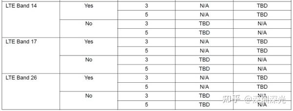
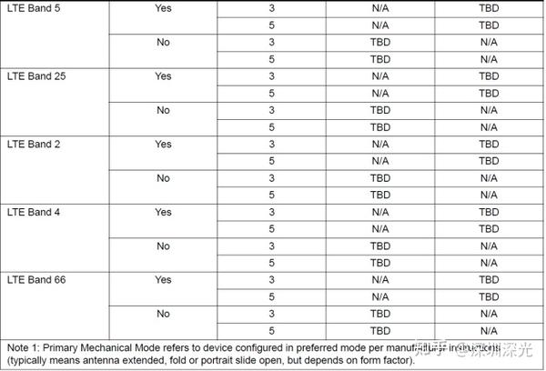
Note: The main mechanical mode refers to the equipment configured as the preferred mode according to the manufacturer‘s instructions (usually it means that the antenna is extended, folded or longitudinally slid open, but it depends on the overall dimensions)
The above is the introduction of LTE Category M1 OTA and LTE NB IOT OTA testing. If you have testing needs in this area, please contact us.
Recommended items
-
PTCRB certification and GCF certification debug analysis
The designed product is PTCRB certified for the first time, and no certified modules are added to the finished product. It is not a deformation certification, not a re-band, not an ECO, etc., so the problems involved in debugging will be deeper. In addition, the examples here only refer to the problems that occur in the Protocol and SIM tests, and other RF and OTA problems do n...View more -

Deeplight |Communication frequency bands of operators around the world
There are three major operators in the People‘s Republic of China (excluding virtual operators), namely: China Mobile, China Unicom, and China Telecom. There are 2 GSM frequency bands, respectively: DCS1800, GSM900. There are 2 WCDMA frequency bands, namely: Band 1 and Band 8. There are 2 CDMA2000 frequency bands, namely: BC0 and BC6. There are 2 TD-SC...View more -

The latest 5G bands recommended by North American mobile operator alliance PTCRB
The division and combination of 5G mobile communication technology is much more complex than 4G. The common large frequency bands are FR1 and FR2, FR1 and FR2 are SA and NSA, NSA is combined with 4G, and the working mode is TDD and FDD, so the confirmation of frequency bands and system is particularly important....View more -

PTCRB certification of finished product of integrated module
Depplight carries on the PTCRB certification program all the year round, and we have a team of sales managers and project managers who have more than ten years‘ experience in dealing with this kind of PTCRB certification and GCF certification programs. Over the years, we have helped many listed companies to obtain PTCRB certification....View more
 +86-13266518903